
Description
Overview
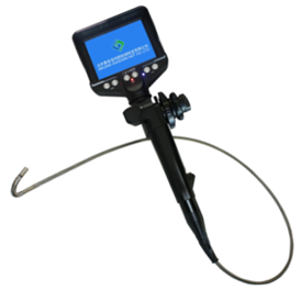
GAOTek Three-Channel Wireless HV CT Ratio Tester is a core technological product which is specific for the on-line measurement and is useful in the detection for primary and secondary current, transformation ratio, error, phase (group) angle difference, polarity, phase sequence, and leaker in the high & low voltage current transformer and the voltage transformers in distribution system under 70 KV (such as 10 kV or 35 kV). It is composed of high voltage detector, three-channel low-voltage secondary current clamps, principal machine, high-voltage insulating rods, monitoring software, communication link, etc. It adopts the wireless transmission signal that is capable of penetrating wall obstacles with a direct-line transmission distance of about 30 m. It is widely applicable to the current detection, abstracting-proof of electricity and field operations of transformer substations, power plants, electrical power inspection departments, industrial and mining enterprises, inspection station, and electrical maintenance departments.
Features
- Current clamp applies the latest CT technology and Double Shielding Technology, for high accuracy, stability, and reliability during continuous monitoring in the entire year.
- Principal machine with the display of four sets of current signals: CT ratio, phase angle difference, and polarity visually in one screen.
- Stores 1,500 sets of data can be set to auto-save interval time to monitor leaker HV detector.
- Breaks the traditional structure with an automatic opening and closing functions which makes it easy to clamp or release measured wire by pressing or pulling back insulating rods
- Extremely safe and time-saving.
- The lightweight insulating rod is characterized by thermo stability, moisture-proof, strong shock resistance & bending resistance high-insulation and high flexibility.
- Monitoring Software with functions such as real-time monitoring, historical data search, accessing, browsing, saving, and printing data available
- Dynamic display integrates the functions of single-channel wireless HV CT tester, HV & LV clamp current meter, HA current remote sensor, HA leaker tester, High accuracy clamp leaker meter, phase detector and three-channel leaker recorder.
Technical Specifications
| Functions | The on-line measurement and detection for primary and secondary current, transformation ratio, error, phase (group) difference, polarity, phase sequence, and leaker in the three-channel high & low voltage current transformer and the voltage transformers |
| Power supply | HV Detector DC6 V alkaline batteries (1.5V AAA × 4)
Principal machine: DC6V alkaline batteries (1.5 V AAA × 4) 30-hour continuous operation available |
| Test mode | Clamp CT, HV 1CT, LV 3 CT double-shield |
| Transmission mode | High-pressure tested data transmitted through wireless network, with a linear transmission distance of 20 m; |
| Range | HV detector 1st: 0.1 mA ~ 1000 A
LV current clamp 2nd: 0.01 mA ~ 10 A |
| Resolution | HV detector: 0.1 mA; LV current clamp: 0.01 mA |
| Primary circuit test accuracy | 0.0 mA~9.99 A: ±1 % ±5 dgt |
| 10.0 A~49.9 A: ±2 % ±5 dgt | |
| 50.0 A~199.9 A:±3 % ±5 dgt | |
| 200 A~600 A: ±4 % ±5 dgt | |
| 601 A~1000 A: ±5 % ±5 dgt | |
| Secondary circuit test accuracy | 0.00 mA~10 A: ±1 % ±5 dgt (three-channel being displayed in one screen 73.4 °F ± 37.4 °F (23 ℃ ±3 ℃), less than 70 % RH) |
| CT ratio | Three kinds of transformation ratio indications :
(1) convert the transformation ratio based on the adjustable basic value of 5 A for secondary circuit current; (2) convert the transformation ratio based on 10 kV-YY of 10 kV/380 V, that means 1st means the current of the line under 380 V, 2nd means the secondary circuit current of CT under the 380 V, and then calculate the ratio between the 10 KV line and the secondary circuit; (3) the measured current ratio can be calculated by the measured CT ratio between the primary and secondary circuit) |
| Reference Range | Reference range of transformation: 0.00 A ~ 99.99 A, the default secondary circuit current is transformed to 5 A; |
| Range of Ratio error
(F.Er) |
0.0 % ~ 9.9 %, the error between the measured CT ratio and the preset CT ratio |
| Range of CT ratio | 0000~9999/0.0 A~9.9 A |
| Range of Ratio error | 0.0 %~ 9.9 %, the principal machine can sound alarm of “beep – beep – beep” if the measured value is more than the preset error. |
| Phase polarity | Symbol Symbol |
| Indication of Phase Sequence | Cursor in clockwise rotation and “Positive Phase” indicated for positive phase sequence. Cursor in counter clockwise rotation and “Negative Phase” indicated for negative phase sequence |
| Indication of Error | Symbol “Error” indicated if the tester can’t identify the phases, polarity, and phase sequence properly; |
| Data Storage | 1500 sets of data memory; press the Left arrow key to select data, and to save and auto-number the selected data (the good condition of data available under power-down or battery replacement) |
| Automatic Recording Interval Time | From 00 minutes to 99 minutes, the tester stops automatic record if being set to 00 minutes; the principal machine doesn’t shut down automatically if being set from 01 minutes to 99 minutes. |
| Sampling rate | 3 times / sec |
| Shift | Full-automatic shift |
| Dimensions | Principal machine: 2.95 in × 6.69 in × 1.18 in (75 mm × 170 mm × 30 mm)
HV detector: 2.99 in × 10.03 × 1.22 in (76 mm × 255 mm × 31 mm) LV current clamp: 2.75 in × 4.52 in × 1.49 in (70 mm × 115 mm × 38 mm) |
| Clamp Size | HV detector clamp: φ1.88 in (48 mm)
LV current clamp: 0.98 in × 1.18 in (25 mm × 30 mm) |
| Voltage | Less than 70 kV voltage for line test(operation by being connected to 5 insolating rods required) |
| Display Mode | LCD: 128 dots × 64 dots;
backlight available for dark areas |
| LCD Size: | 1.73 in × 1.06 in (44 mm × 27 mm) |
| Data Retention | Press the Left arrow key to retain the data ; press the Left arrow key to cancel retention if the symbol “HOLD” displays; |
| Data Search | Press the MEM key and the Arrow key to search data; |
| Overflow Display | Overflow available if being out of range: the symbol “OL A” displayed; |
| Zero-signal indication | The symbol “—” is shown if the principal machine can’t receive the signal from the HV detector; |
| Backlight Control | Available; ON / OFF means to open /close the backlight; |
| Alarm prompt | The principal machine can sound an alarm of “beep – beep – beep” if the measured value is more than the preset error. and press the Right arrow key to launch or stop the alarm function; |
| Auto power-off | Automatic power-off available after about 15 minutes as of starting; |
| Battery voltage | The low- voltage symbol is displayed to remind user to replace the battery if the battery voltage is lower than 4.8 V; |
| Weight | Principal machine: 0.52 lbs (240 g including batteries)
HV detector: 0.73 lbs (335 g including batteries) LV current clamp: 0.33 lbs × 3 (150 g × 3) Total weight: 22.04 lbs (10 kg including instrument box and the insulating rods) |
| Requirements on Interferences | No strong electromagnetic interference; no interference from 433 MHz and 315 MHz channel |
| Operating temperature and humidity | -13 °F ~ 113 °F (-25℃~45℃) less than 80 % RH |
| Storage temperature and humidity | 14 °F ~ 140 °F (-10℃~60℃) less than 70 % RH |
| Insulating rod size | Outer diameter φ 1.25 in (32 mm), inner diameter φ 0.94 in (24 mm), 1 m/piece, 5 pieces |
| Lead length of LV current clamp | 2 m / Piece |
| Dielectric strength | AC100 kV/rms between HV detector cover and the 5th insulating rod; the AC1000 V/rms between the principal machine and the LV current clamp shell between |
| Structure | Anti-leak type II (HV detector) |
Additional Information
Structure

- HV detector clamp (including the boot sectors)
- HV detector booting indicator
- POWER key on HV detector
- Connector of insulating rods 0.94 in (φ24 mm)
- RS-232 interface, for data upload to computer
- POWER key on principal machine
- MEM key and arrows keys
- LV current clamp CT1 Interface
- LV current clamp CT2 Interface
- LV current clamp CT3 Interface
- Principal machine LCD displayer
- LV current clamp output plug
- LV current clamp clips (3 pieces)
- LV current clamp leads
- Insulating rods (5 pieces)
Operations
- Power-on/off of HV detector
Press the POWER key to power on the HV detector, and the POWER indicator lights, the HV detector begins to detect automatically, and transmits the tested data to the principal machine by wireless network. The HV detector can power-off automatically when the POWER indicator flashes continually after about 15 minutes as of booting, and the detector can shut down automatically to save the battery power, after the POWER indicator flashes for 30 seconds. When the POWER indicator flashes continually, press the POWER key to make HV detector in continuous running, and then press the POWER key again to power off.
- Power-on/off of principal machine
Press the POWER key to power on, then LCD begins to display, the principal machine enters the test and receiving mode after a normal booting (see below), 1st means the measured data of the primary circuit on HV terminal, 2nd means the measured data of the secondary circuit on LV terminal, F. Er means the error between the measured CT ratio and preset CT ratio, R, S, and T means the three phases respectively, and the data measured by LV current clamps of CT1, CT2, and CT3 can be displayed on the position of R, S, and T on screen respectively. the LCD can display the symbol “- – -” if the principal machine doesn’t receive the signal from primary circuit; the principal machine can detect the phase and polarity firstly, if receives the data of the primary and the secondary circuit normally, the primary circuit currents are correspondingly visible on the phases of R, S, and T, both the error and polarity can be displayed on the upper left corner of LCD. If the symbol “Err” displays on the upper left corner of LCD display, it is not available to detect the polarity properly, and the measured currents of the primary circuit remain being displayed on the R-phase.


The LCD flashes continually to prompt the soon power off after about 15 minutes as of booting, and the principal machine can shut down automatically to save the battery power, after the LCD flashes for 30 seconds. When the LCD flashes continually, press the POWER key to make the principal machine in continuous running, and then press the POWER key again to power it off
- Test of HV current
If the high voltage detector can be properly connected with 5 insulating rods and starts normally, please set the lead at the center of boot sector on detector clamp (as shown in Figure A). The boot sector on HV detector is perpendicular to the lead, push forward the insulating rod, the lead is clamped by the high voltage detector which starts detecting and feedbacks to the principal machine. Principal machine enters the detection and data collection state after its normal starting up, If the principal machine receives the signal sent by the high voltage detector, the primary circuit current of high voltage end can be shown on R phase, If the principal machine shows that the primary circuit current value is “OL”, it is indicated that the primary circuit current exceeds the upper limit of the high voltage detector. Push the insulating rod backward, the high voltage detector is disconnected with the lead (As shown in figure C). Please do keep the boot sector perpendicular to the lead while removing.
The principal machine can detect the phase (group) differences between the primary circuit and the secondary circuit firstly if receives the signal from the primary circuit, and then determine the polarity under in-phase; and the measured currents of the primary circuit remain being displayed on the R phase if different phases; the primary circuit currents are correspondingly visible on the phases of R, S, and T, under in-group.
- Test LV current
1) Connect three LV current clamps to the corresponding principal machines, power on the machine into the test mode.
2) Vise the measured wires with the LV current clamp (Note: the clip should be fully closed), observe the readings of the secondary current, if the machine displays the symbol “OL A” while detecting the secondary current, it is indicated that the measured secondary current overflows the preset maximum of the LV clamp in the tester, it is recommended to use the HV detector for its measurements. The tester is capable of detecting three-channel or four-channel current /leaker, please operate based on actual requirements.
3) Reference Diagram:

①Recording the circuit current
②monitoring leakers from equipment
③Detecting cable leakers in wall
④Detecting leaker from grounding wire

- Test of CT ratio, polarity
1) TEST OF CT RATIO, PHASE-ANGLE DIFFERENCE, AND POLARITY
As above described, the tester enters into the CT ratio measurement mode after starting, vise the primary and secondary circuit of CT with HV detector and three-channel LV current clamp respectively, and the principal machine displays the four current values in same screen simultaneously, and detects the phase-angle differences and polarity.
For example: The pre-test current transformer is a LV terminal CT of 10 kV/380 V transformer, which primary circuit current is 151.5 A, and which secondary circuit is respectively 2.65 A, 2.50 A, and 2.23 A. It is an in-phase positive polarity between the primary current 151.5 A and the secondary current 2.50 A, the error is +1.0 % (the preset CT ratio is 300/5 A), it is calculated as follows:
[151.5 × (5 ÷ 2.50) -300] ÷ 300 = +1.0 %.
![]() : In-phase positive
: In-phase positive
![]() : In-phase negative
: In-phase negative
Err: Error
2) CT RATIO TEST
Press the Up arrow key to enter the CT ratio displaying mode for a detailed display of the three CT ratios, under the error test mode, and press the Up arrow key from the CT ratio display mode to the error test mode.
For example: The pre-test current transformer is a low voltage terminal CT of 10 kV/380 V transformer, which primary current is 151.5 A, and which secondary current is 2.50 A, it is first to calculate the multiple between the secondary current and the benchmark of 5A; the calculated ratio is 303/5A, [i.e.: 151.5 × ( 5 ÷ 2.50) = 303]; the actual ratio of the primary and secondary currents can be calculated as follows: 151.5 ÷ 2.50 = 60.6; the primary current of 10kV transformer can be calculated based on the benchmark of 10 kV/380 V transformer, and then calculate the CT ratio between the primary and secondary current as follows: [i.e.: 60.6 ÷ (10 kV 380 V) ≈ 2.3].
Press the Left arrow key to move the cursor in the CT ratio display mode, and press the MEM key and the Down arrow key to set the basic value for transformation of secondary current, while calculate the CT ratio on basis of the new basic value. The default basic value of the secondary current is 5A in the tester.

- Detection on phase sequence
It is available to detect LV three-phase sequence, by operating the three-channel LV current clamp of the tester, which is a non-contact measurement for a safe operation under a as follow: dynamic display. Vise each corresponding wire on three phases respectively with the three-channel LV current clamp, CT1 for R, CT2 for S, CT3 for T, the phase sequence is positive if the R-phase angle is 120 ° ± 25 ° more than the S-phase, and the S-phase angle is 120 ° ± 25 ° more than the T-phase, otherwise it is negative. The cursor rotates clockwise on LCD under the positive phase sequence, and rotates counter-clockwise under negative phase sequence, as shown in the figure:

- Alarm launch
Press the Right arrow key to enable or disable the alarm function under the error test mode, the tester can sound a beep if the function is enabled, and displays a small dot on the upper right corner of LCD, otherwise, the small dot isn’t shown when the alarm function is disenabled.
The principal machine can sound an alarm of “beep – beep – beep” under the alarm enable state during the testing process of error if the measured CT ratio error exceeds the preset error, the default setting is to disenable the alarm function after a normal booting each time.
- Data retention and release
Press the Left arrow key to retain the LCD displaying under the error test mode, and the symbol “HOLD” is shown on the screen. And then press the Left arrow key to unlock the data and to return the error test mode, and the symbol “HOLD” disappears.
- Data storage
Press the Left arrow key to retain data under the error test mode, meanwhile, the tester can number and save the current data automatically, and prompt that such an operation is completed. The tester can save up to 1,500 sets of data, if the memory is full; the symbol “Full” is shown, it is necessary to clear the memory for the more storage.
- Data search
Press the MEM key to enter the function menu under the error test mode, and press the Up or down arrow key to move the cursor to the position of “Search data”, then press the MEM key to enter the option, the tester displays the 0001st set of data automatically. Press the Left and Right arrow keys to move the cursor, press the Up or Down arrow key to search date under the change ratio signified by the cursor, the change ratio includes “1, 10, and 100”. Move the cursor to the position of “Return” and press the MEM key to exit the data search mode, and to return the previous menu.
- Data deletion
Press the MEM key to enter the function menu in the error test mode, and press the Up or Down arrow key to move the cursor to the position of “Delete Data”, press the MEM key to enter the option, press the Left or Right arrow key to move the cursor, press the MEM key to delete data or press the MEM key to cancel and return the previous menu.
- Data upload
Connect the RS-232 communication link of principal machine to a computer, and power on the principal machine, boot, and run the monitoring software, if the software displays the serial port is open and connected, it is available to access the historical data, which can be uploaded to the computer and saved under the Text or Microsoft Word format. The monitoring software can be used for the online real-time monitoring, historical queries, and dynamic display, with the functions of reading, browsing, saving, and printing of historical data.
Settings
Press the MEM key to enter the menu under the error test mode, and then press the MEM key to enter the settings. Press the left or right arrow key to move the cursor, move the cursor to the “OK” or “Cancel” key, and press the MEM key to return the previous menu. The Settings menu includes setting CT ratio, setting error, setting time and setting backlight.

As shown in the right figure: Set the CT ratio to 300/5 A; set the error to 3 %; set the automatic recording interval time to 15 minutes; set the backlight to the enable state. Detailed operation is as follows:
- Set CT ratio
The preset CT ratio here refers to the standard transformation ratio on the rating plate of pre-tested current transformer, it is easy to compare with the measured ratio and calculate the error by the above preset, its setting range is from 0000 to 9999 / 0.0 ~ 9.99 A. Press the Left or Right arrow key to move the cursor, press the Up or Down arrow key continuously or interruptedly to change the setting range, move the cursor to the “OK” or “Cancel” position, and press the MEM key to return the previous menu.
- Set error
The pre-set error means the allowable error of the pre-tested current transformer, if the error of measured values is more than the preset error, the principal machine can sound the “beep … beep … beep” alarm, the available setting range is from 0.0 % to 9.9 %, Press the Left or Right arrow key to move the cursor, press the Up or Down arrow key continuously or interruptedly to change the setting range, move the cursor to the “OK” or “Cancel” position, and press the MEM key to return the previous menu.
- Set time
The preset time means the interval time between the adjacent automatic recording operations, which range is from 00 minutes to 99 minutes, the principal machine can shut down automatically if be set to 00 minutes, and the principal machine can’t shut down automatically in the setting range from 01 minutes to 99 minutes. Press the Left or Right arrow key to move the cursor, press the Up or Down arrow key continuously or interruptedly to change the setting range, move the cursor to the “OK” or “Cancel” position, and press the MEM key to return the previous menu.
- Set backlight
Press the Left or Right arrow key to move the cursor, press the Up or Down arrow key to open or close the backlight, ON means to open, OFF means to close, and move the cursor to the “OK” or “Cancel” position, and press the MEM key to return the previous menu.
VIII. Accessories
| HV detector | 1 PCS |
| Principal machine | 1 PCS |
| LV current clamp | 3 PCS |
| Insulating rod (1m/ piece) | 5 PCS |
| Instrument box | 1 PCS |
| Software (disk) | 1 PCS |
| RS232 communication link | 1 PCS |
| Battery (alkali dry battery AAA) | 8 PCS |
| Manual/ Warranty Card/ Certificate of Quality | 1 SET |
