


Description
Overview
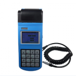
GAOTek Vibration Meter is designed to test conventional vibration in rotating and reciprocating machines, including acceleration, velocity, displacement of vibration and failure diagnosis. It comes with an integrated thermal printer, rechargeable Li-battery 1500mAh, and USB data output.
The built-in software allows the tester to analyze RMS of velocity values, the peak-peak value of displacement and peak values of acceleration using real-time spectral charts. It is also featured with warning limit and alarming limit functions, to remind users that the vibration is beyond the limit of the safe state and destruct status respectively. With a modern and portable design, the GAOTek Vibration Meter has a work capacity of about 50 hours without the need to recharge and it complies with the requirements of GB 13823.3
It is perfect for application in most industrial fields like machinery, power, metallurgy, and automobile.
Features
- Integrated thermal printer to print results
- Designed for vibration tests in rotating and reciprocating machines
- Measures the RMS value of the velocity
- Calculates the peak-peak value of displacement
- Determines real-time spectral charts
- Estimates inherent frequency
- 9 V battery power supply
- Rechargeable Li-battery, 1500 mAh
- USB data output
- Built-in software
Technical Specifications
| Display | TFT320 x 200 pixels with RGB |
| Overall dimension | 8.35in x 3.15in x 1.38in (212mm x 80mm x 35mm) |
| Weight | 0.71lbs (320 g) |
| Tolerance | ±5% |
| Frequency Range | Acceleration: 10Hz ~ 200Hz, 10Hz ~ 500Hz, 10Hz ~ 1kHz, 10Hz ~ 10kHz Velocity: 10Hz ~ 1kHz Displacement: 10Hz ~ 500Hz |
| Speed measuring range | 30 ~ 300000 rpm Corresponding to 0.5Hz ~ 5000Hz |
| Testing Range | Acceleration (peak): 0.01 ~ 20.98 g (0.1 ~205.6 m/s2) Velocity (RMS): 0.01 ~ 15.75 in/s (0.1 ~ 400.0 mm/s) Displacement (peak-peak): 0.1 ~ 354.3 mil (0.001 ~ 9.0 mm) |
| Measuring distance | 0.15m ~ 1m |
| Data memory | 100 x 80 pieces of data and 100 spectrum |
| Data interface | USB |
| Printer | Integrated thermal printer |
| Temperature | 32℉ ~ 104℉ (0℃ ~ 40℃) |
| Battery | Rechargeable Li-battery, 1500 mAh |
| Continuous working time | About 50 hours |
[/tab]
[tab title=”Configurations”]
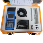
Standard Configuration
| Standard Configuration | NO. | ITEM | QUANTITY |
| 1. | Piezoelectric sensors | 1 | |
| 2. | Main Unit | 1 | |
| 3. | Magnetic seat (with 2 bolts) | 1 | |
| 4. | Package case | 1 | |
| 5. | Power Adapters (input: 220V/50V, output: 9V/1000mA) |
Choose anyone | |
| Power Adapters (input: 110V/50V, output: 9V/1000mA) |
|||
| 6. | Manual | 1 |
Optional Configuration
| Optional Configuration | NO. | ITEM | QUANTITY |
| 1. | Software | 1 | |
| 2. | Communication cable | 1 | |
| 3. | Speed transducer (Lacer) | 1 | |
| 4. | Probe | 1 |
[/tab]
[tab title=”Additional Inofrmation”]
Additional Information
1. General Descriptions
1.1. Basic Working Principle:
The portable vibration tester uses a piezoelectric acceleration transducer to convert the vibration signal into an electric signal. Then by analyzing input signal, results including RMS of velocity values, the peak-peak value of displacement and peak values of acceleration or real-time spectral charts are displayed or printed out.
1.2. Application Range:
The vibration meter is designed to test conventional vibration, especially the vibration test in rotating and reciprocating machines. It can be used not only to test the acceleration, velocity, and displacement of vibration but also perform simple failure diagnosis.
The technical specifications of the tester comply with the requirements of GB 13823.3. It is widely used in machinery, power, metallurgy, automobile and other industrial fields.
2. Technical Terms:
- Vibration: A rapid linear motion of object about an equilibrium position, like a piston, tuning fork or motor.
- Vibration displacement: The magnitude of a vector from the initial position to a subsequent position assumed by a body.
- Vibration velocity: The rate of speed of vibration.
- Vibration acceleration: The rate of change of vibration velocity with respect to time.
- Vibration frequency: The number of complete cycles of vibration per unit time.
- Point number: One point number corresponds to one testing point.
- Patrol test: Test more than one point in a fixed routine. Each point corresponds to one testing point.
- Warning limit: Remind users that the vibration is beyond the limit of the safe state.
- Alarming limit: Remind users that the vibration is beyond the limit of the destruct status.
- RMS, peak values and peak-peak values (see Figure 2-1).
- Spectral chart: A chart indicates the magnitude distribution of each frequency in the whole vibration.

Figure 2-1
3. Configuration:
Description of components

Figure 3-1
- Socket of transducer
- Socket of USB
- LOGO
- Paper compartment cover
- Viewing Area
- Keypad
- Battery switch
- Power jack
- Vibration transducer
- Connect Bolt
- Magnetic base
- Probe groupware 13.Laser transducer
According to different situations, the transducers may be fixed in the probe groupware or connected to the magnetic base (see chapter 4 in detail.).
4. Installation of Transducer:
4.1 Installation Principle:
- The testing position should show the vibration characters of the object to be tested.
- The main axis of the transducers should be consistent with the direction of the object to be tested.
- The transducers should be in close contact with the object to be tested.
4.2 Install Method:
| Install Method |
Install with bolts | Install with magnetic base |
Install with probe |
| Contrast | |||
| Cost | None | Low | Rather high |
| Affection on the result | None | When roughness is worse than Ra1.6, the result may be not stable. | When caring about acceleration and the vibration frequency is higher than 1KHz, the result will be smaller. |
| Convenience | Not good | Good | Best |
4.2.1 Installed with Bolt:

Figure 3.2
4.2.2. Installed with a Magnetic Base:
Application range: Magnetic, flat surface, roughness less than Ra1.6, acceleration less than 20 m/s2.
Usage: Before using, take off the iron wafer and rubber wafer under magnetic base (ensure enough suction), adsorbed on the object being tested and then screw up the magnetic base on transducer (see Figure 4-2). After usage, put back the iron wafer and rubber wafer to maintain the magnetism.

Figure 3.3
4.2.3 Installed with Probe:
Applications range: Frequency is less than 1KHz; vibration energy is not too small. Usage: Connect the needle to the transducer directly by using probe groupware (see figure 4-3)

Figure 3.4
4.3 System Operation:
In this chapter, it gives a brief introduction of keys (refer to Table 4.1) and menu (Figure 4.2)

Table 4.1
Description:
- Power: Press
 to switch on/off the meter.
 - Measure: Press
 to enter into measurement, and Press
 to end measurement; if the “Auto Save” is on, then autosave the measure data, or Press
 to save the measured data
 - Data Delete: Press
 to delete the stored measurement result.
 - Data View: Press
 to review the stored measurement result.
 - Paper feed: Press
 to feed the paper.
 - Data Print: Press
 to print the current measurement result or the stored measurement result.
 - Point patrol: Press
 to switch on/off the point patrol function.
 - Measure model: Press to select the measure model: Common model, Spectrum model and Rev model (refer to Figure 4.1a, Figure 4.1b, Figure 4.1c).

Figure 4.1a Common mode

Figure 4.1b Special mode

Figure 4.1c Rev mode
- Measure parameter: Press
 to select the measure parameter: Acceleration, velocity, and displacement. (Refer to Table 4.2).
Table 4.2 reference table for measurement parameters
| Main parameters | Acceleration | Speed | Displacement |
| Available transmission bands | 10-200Hz 10-500Hz 10-1kHz 10-10kHz |
10-200Hz 10-500Hz 10-1kHz |
10-200Hz 10-500Hz |
| Default warning limit | 200 m/s2 | 400 mm/s | 0.393 in (10.0mm) |
| Default alarm limit | 200m/s2 | 400 cm/s | 0.393 in (10.0mm) |
- System parameters setting: Press to enter into main menu, Press and to select submenu, Press to confirm operation or enter into submenu. Press to cancel or return the last menu (refer to Figure 4.2).

Figure 4.2
Battery indicator: display the remaining electric quantity.
| Operation tips: when the battery is low, please charge it in time, or it will cause the accuracy of the measurement. |
Measuring status: there are measurement and non-measurement mode; In measurement status, the process bar will display “█ █ █”;
In non-measurement status, it will display the latest measurement time, for example, “09:20”; Time: display the current system time
Point number: the point number related to the current measured information
Display area: there are three display modes, including common, special and spectrum.
Common mode: show the main parameters (see figure 4.1a)
Spectrum mode: show the spectrum chart (see figure4.1b)
Rev mode: show the Rev value (see figure 4.1c)
Main parameters: select velocity, displacement, and acceleration
Transmission bands: after the selection of the main parameters, users can select the corresponding bandwidth.
Warning limit: you need to preset the warning limit and alarm limit. During measurement, if you select common and Spectrum mode, when the measured value is higher than the warning limit, the system will prompt to alarm.
| Operation tips: (1) If the preset of warning value exceeds the preset of alarming value the system will set “warning value” =“alarming value” automatically. (2) If the preset value exceeds the default value of table 4.2, system will set “preset value”=“default value”. |
4.3.1 Point Patrol:
If point patrol is disabling, the point number will not increase automatically. When tests are performed continuously, the measurement results will be regarded as different testing results of the same testing point number.
If point patrol is enabled, when a testing operation of the current point number is finished, the point number will increase automatically, and go into the waiting state of the next point number. Up/Down keys can also change the testing point number. For example, after point number 1 measurement is finished, the system will automatically enter the point number 2 and wait for measurement, after the second measurement, it will automatically enter point number 3. It is much more convenient when you need to perform continuous measurement of many points.
4.3.2 Time Setting:
This tester can automatically record the time when the test is performed. If the time is not correct, it should be reset manually.
4.3.3 Software Information:
It displays the software version and serial number
4.4 Analyze:
Figure 4.3 shows that the “Analyze” menu consists of “Print”, “Auto”, “Manual” and “Zoom” four sub-items. Figure 4.3 shows the analysis interface.

Figure 4.3
4.4.1 Print:
The currently displayed spectrum chart can be printed.
4.4.2 Auto:
Press![]() or
or![]() to move the cursor and the system will automatically capture the peak value and the corresponding frequency as well as amplitude.
to move the cursor and the system will automatically capture the peak value and the corresponding frequency as well as amplitude.
4.4.3 Manual:
The values of different points in the charts can be looked through in the manual style. Press![]() and
and![]() to move cursor to display the frequency and amplitude of the point which the cursor pointed.
to move cursor to display the frequency and amplitude of the point which the cursor pointed.
4.4.4 Zoom:
In spectrum analysis, the spectrum zoom function can change the frequency resolution in the range selected by users. Firstly, to select the range of the frequency—-that is the concerned area, press![]() or
or![]() keys to move the cursor. The cursor could move more quickly when the
keys to move the cursor. The cursor could move more quickly when the![]() or
or![]() key is held. Secondly,
key is held. Secondly, ![]() and
and![]() keys could change the frequency resolution. The resolution could reach 0.25Hz.
keys could change the frequency resolution. The resolution could reach 0.25Hz.
4.4.5 View:
Users can look through the measurement results stored in the memory by press/key. The information of each measurement result comprises point number, testing time, certain results, unit and whether the measured results are higher than the warning limit. Users could print out the list. Also, the data can be deleted.
5. How to Use the Accessories:
The tester has accessories such as printer and corresponding software. If equipped with a printer, the printing operation can be performed. The data stored in the tester can be uploading to PC and analyze with corresponding software. If the PC is equipped with a printer, the data can also be printed out from the PC. The tester connects to a printer or PC through a communication cable. One end is connected to it through RS232 serial port, and the other end is connected to the printer or PC through a 9-pin connector. How to use the software can refer to the specifications of the corresponding software.
6. Troubleshooting:
- When the battery cannot charge, check the charging indicating light.
- The measurement value is unstable.
- Make sure the vibration frequency of the vibration object is in the frequency range of 10Hz—10 kHz.
- If the magnetic base is used, pay attention to:
- Make sure the surface of the tested object is flat, and roughness is smaller than Ra1.6.
- Make sure the iron wafer below the magnetic base is taken off, and the magnetic force is enough.
- When entering the non-mother language system because of incorrect operation, users can change back the mother language referring to the construction of the menu (see 5.3). If some trouble cannot be overcome, please contact us.
7. Maintenance:
- Operating environment: Strictly avoid collision, heavy dust, dampness, strong magnetic field, oil, grease, and dirt.
- How to clean the main body of the meter: Because alcohol and other chemical liquid can erode the main body of the tester, especial the display window, little water can be used to clean to meter smoothly.
- How to use the connector: Don’t plug the connector of the transducers, printer or PC, when tester is power on.
- Calibration: The vibration meter is a high-precision instrument and the environment will influence it. So it should be calibrated periodically (half a year or one year). If the sensitivity has changed, it can be adjusted by rotating the knob which is used to adjust the sensitivity.
- Electromagnetic influence: when the electromagnetic field is over 10 V/m, the accuracy of testing will be influenced.
c8. Non-warranty Parts
Appendix 1: Vibration standard
a. Rank of Machine Vibration (ISO2372):
| Vibration amplitude | Machine sort | |||
| Vibration Velocity Vrms (mm/s) |
Ⅰ | Ⅱ | III | IV |
| 0~0.28 | A | A | A | A |
| 0.28~0.45 | ||||
| 0.45~0.71 | ||||
| 0.71~1.12 | B | |||
| 1.12~1.8 | B | |||
| 1.8~2.8 | C | B | ||
| 2.8~4.5 | C | B | ||
| 4.5~7.1 | D | C | ||
| 7.1~11.2 | D | C | ||
| 11.2~18 | D | |||
| 18~28 | D | |||
| 28~45 | ||||
| >45 | ||||
Note:
- Class I is a small motor (power less than 15kW). Class II is a medium motor (power between 15kW~75kW). Class III is a high power motor (hard base); Class IV is a high power motor (stretch base).
- A, B, C, D are vibration rank. “A” means good, “B” means satisfying, “C” means not satisfying, “D” means forbidden. Vibration velocity should be taken from the three perpendicular axes on the motor shell.
b. Maximum Vibration of Motor that Power Larger than 1 Horsepower (NEMA MG1-12.05)
| Rev (rpm)
|
Displacement (p-p) | |
| Inch | μm | |
| 3000~4000 | 0.001 | 25.4 |
| 1500~2999 | 0.0015 | 38.1 |
| 1000~1499 | 0.002 | 50.8 |
| ≤999 | 0.003 | 63.6 |
* For AC motor, rev is maximum synchronous rev. For DC motor, it is maximum power rev. For motor in series, it is work rev.
c. Maximum Vibration of High-power Induction Drive Motor (NEMA MG1-20.52)
| Rev (rpm)
|
Vibration displacement (p-p) | |
| Inch | μm | |
| ≥3000 | 0.001 | 25.4 |
| 1500~2999 | 0.002 | 50.8 |
| 1000~1499 | 0.003 | 63.6 |
| ≤999 | 0.003 | 76.2 |
*National Electric Manufacturers Association (NEMA) establishes two standards above.
c. Maximum Vibration of Squirrel-cage Induction Drive Motor (API STD 541)
| Synchronous rev (rpm)
|
Vibration displacement (p-p)(um) | |
| Stretch base | Hard base | |
| 720~1499 | 50.8 | 63.6 |
| 1500~2999 | 38.1 | 50.8 |
| ≥3000 | 25.4 | 25.4 |
*American Petroleum Institute (API) established this standard.
d. ISO/IS2373 Motor Quality Standard According to Vibration Velocity.
| Quality rank | Rev (rpm) | H: High of shaft (mm)
Maximum vibration velocity (rms)(mm/s) |
||
| 80<H<132 | 132<H<225 | 225<H<400 | ||
| Normal (N) | 600~3600 | 1.8 | 2.8 | 4.5 |
| Good (R) | 600~1800 | 0.71 | 1.12 | 1.8 |
| 1800~3600 | 1.12 | 1.8 | 2.8 | |
| Excellent (S) | 600~1800 | 0.45 | 0.71 | 1.12 |
| 1800~3600 | 0.71 | 1.12 | 1.8 | |
The limit of rank “N” is suitable for common motor. When the request is higher than that in the table, the limit can be gotten by dividing the limit of rank “S” with 1.6 or multiples of 1.6.
Appendix 2 Vibration Frequency and Possible Reason:
| Vibration
frequency |
Most possible
Reason |
Other possible reason | Note |
| Synchronous with fs * | Imbalance |
|
|
| Double fs | Mechanical loose |
|
|
| Triple fs | Not in middle | ||
| N multiple of
fs |
Gear fault, liquid force, mechanical
loose, reciprocating force |
1×N× fs (N is the tooth number of the fault gear).
2×N× fs (N is the paddle number of the fault pump or fan) |
If loose is worse, there may be a higher multiple frequencies. |
| < fs | Oil film eddy turbulence |
|
|
| Synchronous with power frequency | Armature fault | Electric fault such as rotor broke, rotor eccentric, three-phase imbalance and air clearance, not symmetry | |
| Double the power frequency | Torsional impulse | Seldom | |
| High frequency (not multiple offs) | Shaft is not lubricate |
|
Amplitude and frequency of vibration are always not steady. |
* fs is the frequency according with the rev of the main shaft