Description
Overview
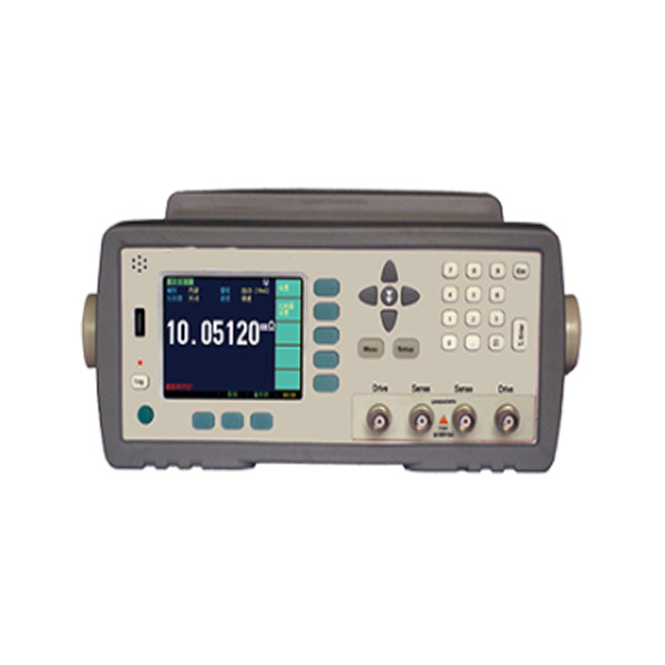
GAOTek Micro Ohm Meter with temperature compensation is used to test super low or low resistance and has an accuracy of 0.1 % with measurement range 0.1 µΩ to 1 GΩ and has built-in temperature compensation interface to compensate the error caused by temperature. This Micro Ohm Meter has an excellent repeat measurement, break through the resistance value display of 6.5dgts, has 1,200,000 reading, the maximum sampling rate is 4.5 ms. This ohm meter has a built-in 14 bins of comparator output, can setup 10 GD bins, and all bins comparator results can be output by Handler interface. The instrument has RS-232 interface, adopts SCPI to communicate with PC, PLC or WINCE equipment, in order to efficiently realize remote control and data acquisition function. It is applied in measuring low resistance, shut and contact resistance with high speed test.
Key Features
- Temperature compensation function
- High current ( open circuit < 20 mV)
- Excellent repeat measurement accuracy
- Keypad lock function
- Data hold function
- Comparator and data output function
- Correction Function
- Built-in RS-232C, Handler (EXT-I/O) Interfaces
- Adjustable Beeper and display
- Internal, Manual, External and Remote Trig
- GPIB Interface (Optional)
- SCPI compatible command sets
- Keypads lock function
- Data Hold function
- Four-terminal resistance test
- HI/IN/LOW/GD/NG sorting results display and output
- Self-Calibration: Thermo-electromotive force compensation
- Measurement Speed: Ultra2 (Display Off): 220 readers/second (4.5 ms)
- Trigger Mode: Manual, Internal and External
- Double display: ΔABS/Δ/Sorting Result
- Zero-setting Function: Zero-Adjust for each range
- Comparator Function: (Stores up to 30 group comparators)
Technical Specifications
| Parameters | DC voltage |
| Range | Automatic and manual with 11 ranges |
| Speed | 167 times / second, 30 times / second, 10 times / second, 2 times/ second |
| Resistance Measurement Range | 0.1 µΩ to 1 GΩ |
| Measurement Current | 1 A to 1 Am1 |
| Accuracy | 0.1 % |
| Display | Show ABS, % sorting result |
| Display Max | 120,000 |
| Adjustment | Open and short reset for each range |
| Comparator | 14 groups record, NG-LO, GD-IN,NG-HI display and output, adjustable beep and volume |
| Trigger | Internal, manual, external and remote |
| Range | 6 ranges with Auto, Manual and Nominal Modes |
| Interface | RS 232 C, Handler interface (PLC interface) |
| Temperature Compensation | Accuracy: 32.36 °F (0.2 °C) Range: 32 °F- 176 °F (0 °C~80 °C) |
| Method | 4 terminal shielding(2 check terminal and 2 driving terminal) and external shielding ground section |
| Voltage: | 198 V AC – 240 V AC Frequency: 50 Hz/60 Hz Power: Max 15 VA |
| External Size | 10.39 in (264 mm) x 4.21 in (107 mm) x 13.77 in (350 mm) |
| Inside size: | (W) 8.50 in (216 mm) x (H) 3.46 in (88 mm) x (D) 12.71 in (323 mm) |
| Range | -50 °C to 650 °C (-58 °F to 1202 °F) |
| Resolution | 0.1° < 1000°, 1°> 1000° |
| Accuracy | -58 °F to -10 °F (50 °C to -23 °C) 14 °F (±7 °C) (Typical)
-10 °F to -28.4 °F (-23 °C to -2 °C) 8°F (±4 ° C ) 28 °F to 200 °F (-2 °C to 94 °C) 4 .5 °F (± 2.5 °C) 200 °F to 400°F ( 94 °C to 204 °C) ± (1.0% rdg + 1°C/2 °F) (204 °C to 426 °C )400 °F to 800 °F ± 1.5 % rdg + 1 °C/ 2 °F (426 °C to 1050 °C) 800 °F to 1922 °F ± (3 %r dg +1 °C/2 °F) Note: Accuracy is specified for the following ambient temperature range: 73 °F to 77 °F (23 °C to 25 °C)
|
| Emissivity | 0.10 to 1.00 adjustable |
| Field of View | D/S = Approx. 12:1 ratio (D = distance; S = spot or target) |
| Laser pointer | Dual, Class 2 laser < 1mW power; Wavelength is 630 nm to 670nm |
| IR Spectral response | 8 pm to 14 pm (wavelength) |
| Repeatability | ± 0.5 % of reading or ± 1°C (1.8 °F) whichever is greater |
| Display | Backlit LCD display with function indicators |
| Response time | 150ms |
| Operating Temperature | 32 °F to 122 °F (0 °C to 50 °C) |
| Operating Humidity | 0 % to 90 % RH operating, <80 %RH storage |
| Storage Temperature | 14◦ F to 140 °F (-10 °C to 60 °C) |
| Power Supply Automatic | 9 V battery |
| Power Off Weight | 7 seconds, with LOCK to disable 0.33 lbs
(150 g)
|
| Dimensions | 7.98 in x 4.21 in x 1.57 in (180 mm x 107 mm x 40 mm) |
| Weight | 7,71 lbs (3.5 kg) |
| Temperature and humidity range: | 59 ◦ F to 95 ◦F (15 ◦C to 35 ◦C), 80 % RH or less |
| Storage temperature and humidity range: | 50 ◦ F to 104 ◦F (10 ◦C to 40 ◦C), 10 % to 90 % RH |
Application
- Suitable for all kinds of high, middle and low resistor
- Contact resistance of the switches
- Contact resistance of all kinds of connector
- Resistance of motor and transformer
- Windings
- Enamel-insulated wire resistance
- Relay/switch connector contacts
- PCB patterns
- Chip inductor DC resistance
- Wire Resistance
- Car, Ship and plane fasten or secure resistance
Main Specifications
Ranging
There are three types of range i.e. Auto, Hold and Nominal range. Total 12 Ranges about Nominal ranges: The instrument will automatically select the best range according to the nominal value. 2.2.2
Measurement Speed
- Ultra2 (Display Off): 220 readers/second (4.5 ms)
- Ultra: 130 readers/second (7.7 ms)
- Fast: 50 readers/second (20 ms)
- Medium: 10 readers/second (100 ms)
- Slow: 2 readers/ second (500 ms)
Trigger Mode
- Internal Trigger
- Manual Trigger
- Bus Trigger
- External Trigger
Basic Accuracy
- Slow Speed: 0.01 %
- Medium Speed: 0.05%
- Fast and ultra-speed 0.01 %
Main Functions
Correction Functions:
- Short Correction: Eliminates measurement errors due to stray parasitic impedance in the text fixtures
- Comparator Function (Sorting)
- Bin Sort
- The primary parameter can be sorted into BIN1-BIN9, and HI/IN/LO
- The sequential mode or tolerance mode can be selected as the sorting mode
Limit Setup
Absolute value, deviation value, and % deviation value can be used for setup
Front Panel Summary

Front panel description
| No. | Description |
| 1 | USB Disk Port (USB-Host) |
| 2 | Trigger Key |
| 3 | Power Switch |
| 4 | System Key (Include File, System and Key Lock) |
| 5 | Soft Key |
| 6 | Menu key |
| 7 | UNKNOWN Terminal |
| 8 | Entry Key |
| 9 | Cursor Key |
| 10 | LCD Display |
Real Panel

| No. | Description |
| 1 | RS-232C Interface |
| 2 | Handler Interface |
| 3 | Temperature Compensation Interface |
| 4 | AC Power Cord Receptacle |
Connect to Device under Test (DUT)

<MEAS DISPLAY> Page
When press the [Meas] key, the <MEAS DISPLAY> page appears.
The following measurement controls can be set
- TRIG – Trigger Mode
- COMP – Turn the comparator ON/OFF
- RANGE – Measurement Range
- SPEED – Measurement Speed

Trigger Mode [TRIG]
| SCPI Command: | TRIGGER: SOURCE {INT,MAN,EXT,BUS} | |||||||||||
It supports four trigger modes: INT (internal), EXT (external), MAN (manual) and BUS (RS-232)
|
||||||||||||
Comparator Bins [COMP]
SCPI Command: Comparator [: State] {Off, ##-BINS}
While the comparator function is OFF, sorting system will no longer work and the Handler interface signals on the comparator output will be shut down.
Short Circuit Clear Zero
SCPI Command:
The short correction feature of compensate for any residual resistance that may exist within the interval from the calibration plane, which is determined by the selected cable length, to the DUT connecting points.
Residual Resistance

<Comparator> Page
Press [Setup] key and press [Comp Setup] soft key to open <COMPARATOR>page.

Comparator limit mode [MODE]
SCPI Command: Comparator: MODE {ABS, PER, SEQ}
You can specify the primary parameter limit values in one of the following 2 ways:
Tolerance mode [%]
In tolerance mode, the comparison limit values are based on the deviations from the specified nominal value, which can be specified in the [NOM] field. You configure the tolerance mode limit values as a deviation percentage (%) or absolute parameter value.
Sequential mode [SEQ]
In sequential mode, the comparison limit values are based on the absolute value of the measurement. When you configure these limit values, you have to first define the minimum value and then the maximum value.

- Includes the point
- Excludes the point
Absolute value () = UNKNOWN value – nominal value
Deviation percentages (%) = Absolute value () / nominal value × 100%
In Sequential mode, the comparison limit values are based on the absolute value of the measurement. The nominal value does not need to participate in operation.
To set up the comparator limit mode
Step 1.Press the [Meas] or [Setup] key
Step 2.Press the [COMP SETUP] soft key
Step 3.Use the cursor key to select [MODE] field
Step 4.Use the soft keys to select comparator mode
Nominal value for tolerance mode
Comparator : NOMINAL <float>
You must configure the nominal value when you use tolerance mode as the limit mode. In sequence mode the nominal value does not affect sorting. In sequential mode you can configure nominal value or not, but if you have set the Range Mode to [NOM] the Nominal value must be configured.
Lower and Upper Limits
SCPI Command: Comparator: BIN < 1 to 10>, <LOWER>,<UPPER>
It’s a built in comparator can cord DUTs into a maximum 10 levels (Bin1 thru Bin10
Electrical Characteristics:
Input Signal:
Each h signal is connected to the LED (cathode side) of the photo-coupler. The LED (anode side) is connected to the pull-up power supply voltage
Output Signal:
Each output signal is 5 kΏ (0.1 W) resistors by using outputted via a pull-up a photo-coupler.
Power Supply
The power supply for the judgment output signal pull-up and that for the operation output signal pull-up and input signal drive can be set separately. You can select from + 3.3 V to + 35 V external power supply. An interval VCC (5 V DC) has been supplied for testing purpose.
To using the internal power, please connect PIN- 34 and PIN -35 together and PIN -35 together and PIN -29 together.
Dimensions


