Description
Overview
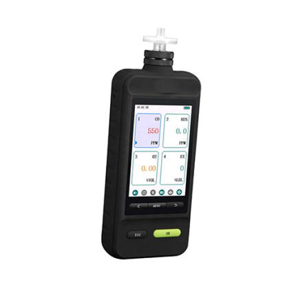
GAOTek ‘Four Gas Detector with High Accuracy (Dust-Proof, Data Store)’ is a portable multi-gas detector. It continuously monitors four types of gases: O2, LEL (combustible gas), CO, H2S. It also provides four kinds of sensor type customization. Users can match any of the four according to their needs to select the sensor. Each gas concentration degree will be displayed on the TFT color liquid crystal. The instrument provides a user-settable low concentration of self/high alarm and STEL/TWA alarms. The instrument uses a new generation of imported toxic gas sensors, PID photo-ionization sensors, catalytic combustion of combustible gas sensor and independent research and development of infrared gas sensors. It is safe and reliable providing security for the staff from poisonous gases in dangerous environment.
Key features
- Small size, light weight and easy to carry
- High accuracy, short response time, wide measurement range
- Large screen color LCD graphic display
- USEI rechargeable lithium battery with long life for fast and easy charging
- Built-in large capacity memory stores large amounts of measurement data
- Powerful sound and light alarm with vibration alarm variety of alarm mode
- Water proof, dust proof, explosion proof and rugged enclosure drop resistance protection
- Supports USB and the upper machine communications
- Ppm and mg/m³ unit switch
- Warning lights flashing makes it convenient to work in the dark
- Password to restrict and protect the configuration menu changes
Technical Specifications
Product type | Portable multi-gas detector |
Sensor type | Toxic electrochemical, catalytic combustion of combustible gas, PID photo-ionization, ad hoc research and development of infrared gas sensor |
Battery | Built-in rechargeable lithium battery (3.7 V, 3000 mA) |
Operating hours | Fully charged for longer than 20 hours |
Charging time | Less than 4 hours |
Display | TFT colorful screen |
Alarm | Audible alarm, a red LED light alarm, vibration alarm |
Keyboard | 4 keys |
Sampling way | Diffused type |
History record | 30-second intervals can store more than one month record |
Alarm record | 200 alarm recording, loop record |
Calibrate | 2-point calibration, you can set the nominal concentration |
Operating Temperature | -4 °F ~ 131 °F (-20 ℃ ~ 55 ℃) |
Working Humidity | 0-95 % RH (non-condensing) |
Size | 5.11 in × 3.14 in × 1.65 in (130 mm × 80 mm × 42 mm) |
Weight | 0.66 lbs (300 g) |
Warranty | 1 year |
Additional Information
Ordering Information
Product Selection
Model Number | Product Type | Electro chemical sensor | Combustion catalytic sensor | PID sensor | Infrared Sensor |
GT00Z200XB | PRO | 3 kinds | Yes | No | No |
GT00Z200XB-A | PRO-EC | 4 kinds | No | No | No |
GT00Z200XB-B | PRO-PID | 2 or 3 kinds | Optional | Yes | No |
GT00Z200XB-C | PRO IR | 2 or 3 kinds | Optional | No | 1 or 2 kinds |
GT00Z200XB-D | PRO PID+IR | 1 or 2 kinds | Optional | Yes | 1 or 2 kinds |
Electro-chemical sensor order and parameter table:
Gas Type | Range | Low alarm value | High alarm value | TWA value | STEL value | Unit |
LEL | 0-100 %LEL | 25 | 50 | – | – | %LEL |
CO | 0-500 PPM | 35 | 200 | 35 | 200 | PPM |
H2S | 0-50 PPM | 10 | 15 | 10 | 15 | PPM |
NH3 | 0-100 PPM | 25 | 50 | 25 | 35 | PPM |
SO2 | 0-20 PPM | 2 | 5 | 2 | 5 | PPM |
NO2 | 0-20 PPM | 3 | 5 | 5 | 5 | PPM |
CL2 | 0-20 ppm | 0.5 | 1.0 | 0.5 | 1.0 | ppm |
Br2 | 0-20 ppm | 0.1 | 0.5 | 0.1 | 0.5 | ppm |
CLO2 | 0-20 ppm | 0.1 | 0.2 | 0.1 | 0.3 | ppm |
PH3 | 0-5 ppm | 0.3 | 1.0 | 0.3 | 1.0 | ppm |
HCL | 0-20 ppm | 2.0 | 5.0 | 2.0 | 5.0 | ppm |
HBr | 0-20 ppm | 2.0 | 5.0 | 2.0 | 5.0 | ppm |
HCN | 0-100 ppm | 4.7 | 10.0 | 4.7 | 10.0 | ppm |
H202 | 0-100 ppm | 1.0 | 3.0 | 1.0 | 3.0 | ppm |
ETO | 0-20 ppm | 1.0 | 5.0 | 2.0 | 5.0 | ppm |
CH2O | 0-5 ppm | 0.1 | 0.3 | 0.1 | 0.3 | ppm |
COCL2 | 0-1 ppm | 0.1 | 0.3 | 0.1 | 0.3 | ppm |
NO | 0-100 ppm | 25 | 50 | 25 | 50 | ppm |
SiH4 | 0-50 ppm | 2.0 | 5.0 | 2.0 | 5.0 | ppm |
O3 | 0-5 ppm | 0.1 | 0.3 | 0.1 | 0.3 | ppm |
H2 | 0-1000 ppm | 200 | 500 | 200 | 500 | ppm |
O2 | 0-25 %vol | 19.5 | 23.9 | – | – | % |
C2H4 | 0-200 ppm | 20 | 50 | 20 | 50 | ppm |
Sensor order and Parameter table:
Order numb-er | Label Color | Range | Resolu-tion(ppb) | Respo-nse Time(sec) | Low alarm value | High alarm Value |
PID-10000 | Green | 10000 | 100 | < 3 | 1000 | 4000 |
PID-2000 | purple | 200 | 500 | < 3 | 200 | 600 |
PID-200 | red | 200 | 50 | < 3 | 20 | 60 |
PID-20 | yellow | 20 | 5 | < 3 | 2 | 8 |
PID-2 | blue | 2 | 0.5 | < 3 | 0.5 ppm | 1.0 ppm |
IR Sensor order and parameter table:
Order number | Gas Type | Series | Model Number | Range | Resolution |
IRCH4-5 | CH4 | A | CH4-5/A-5 | 0-5 % VOL | 0.01 % VOL |
IRCH4-100 | CH4-5/A-100 | 0-100 % VOL | 0.1 % VOL | ||
IRCO2-1 | CO2 | B | CO2/B-1 | 0-1 % VOL | 0.001 % VOL |
IRCO2-10 | CO2/B-10 | 0-10 % VOL | 0.01 % VOL | ||
IRCO2-20 | CO2/B-20 | 0-20 % VOL | 0.01 % VOL | ||
IRCO2-100 | CO2/B-100 | 0-100 % VOL | 0.1 % VOL | ||
IRHC-5 | HC | C | HC/C-5 | 0-5 % VOL | 0.01 % VOL |
IRHC-100 | HC/C-100 | 0-100 % VOL | 0.1 % VOL |
IR Sensor order and parameter table:
1. Appearance of the instrument
The instrument includes a display screen, four highlighted alarm LED lights, a charging indicator light, buzzer and four action buttons. The display displays a variety of test data and instrument status information. The charge indicator indicates the charge state. USB interface can be used to charge as well as to connect with the host computer. Built-in vibration motor which makes the alarm vibrate, allows users to more easily use in noisy environments.
2. Parts of the instrument assembly drawing
①: screw stopper ②: Screw ③: the lower lid ④: Sensor Board
⑤: sensor plate ⑥: Sensor ⑦: cover ⑧: Calibration cover
⑨: Calibration cover fixing screw
3. Charge
The instrument should be charged before using. It can be charged via the USB interface. Please pull out the USB soft plug before charging, connect USB charger and the instrument automatically starts charging. During charging, the indicator light is red and it turns green after it is complete.
When the battery voltage is less than the operating voltage, the instrument will automatically shut down. In this case the instrument cannot boot and you must connect the charger before use.
Unplug the USB rubber plug at the bottom of the instrument
When the battery is less than 20 % and less than 10 %, the buzzer starts sounding and the power indicator on the LCD screen gives out a red low-battery warning symbol. When the battery is running out, the instrument automatically shuts down and powers off in 3 seconds.
4. Battery use
Battery performance is affected by many factors, including sensor type, instruments’ temperature and the chosen or used functions or settings.
In order to achieve optimal battery performance, observe the following rules:
- A new battery or unused battery takes a long time to charge
- While charging, keep the battery at or near room temperature
- High temperature, exposure and other factors will reduce battery life. Try to avoid this type of environment.
- After long-term use, the battery will gradually wear out and needs to be changed. You need to buy original batteries or batteries approved by the Company as inferior parts can damage equipment and cause danger!
5. Instrument startup and shutdown
Start Up
Press and hold the power button for more than three seconds, the instrument automatically turns on. Boot the speaker alarm. The instrument self-tests for 90 s and shows the concentration detection interface.
If the following conditions occur, press the power button for 3 seconds to restart the device.
- The buzzer does not sound
- Vibration alarm does not work
- LED does not light Indicating an error
Shutdown
In addition to the instruments’ preheat mode, regardless of the instrument being in any other mode, hold down the switch button for 5 seconds, release the button, the screen is off, the instrument is turned off.
6. Operation of the instrument
6.1 Overview of Operation
During normal use, there are two modes of operation: normal mode, program mode. Conventional mode is the mode to enter after the start of the instrument, also called measurement mode. After booting, the instrument automatically enters the normal mode to measure gas concentration, displays the current measured gas concentration.
Programming mode: After entering the mode menu in programming mode, you can change various parameters of the instrument. In the programming mode, you can zero and span calibration. Under normal circumstances, you can use the normal mode.
6.1.1 Conventional mode
Normal mode: The instrument enters the normal mode boot default. In the normal mode, the instrument has a real-time display of gas concentration measurement, the measuring data recording. Within this mode, you can display the battery power, gas type, current real-time concentration, concentration units, and time.
6.1.2. Programming mode
Programming Mode: In measurement mode, press [OK] key to enter the programming mode. 6 sub-menus display the programming mode, enter each menu, you can make various types of parameters.
Enter the programming mode, the cursor appears in the first item “Calibration” and press [up and down] keys to move the cursor to the next item, press the [OK] key to enter the submenu. Press [Back] key to return to the measurement mode.
There are six function main menu in programming mode, each for: parameter setting, gas calibration, alarm settings, language settings, history, system settings. And other functions. Main menu and sub-menu content in programming mode as follows:
Parameter setting
|
Gas calibration
|
Alarm settings
|
Language settings
|
History, system settings
|
System settings
|
1.Gas type | 1.Zero | 1.Lower value alarm | Language setting | 1.History record | 1. Address setting |
2. Decimal | 2.Range calibration | 2.High value alarm | 2.Alarm record | 2.Backlit light | |
3.Range | 3.Restore default | 3.STEL | 3.Clear record | 3.Backlit time | |
4.Gas unit | 4.ADC value | 4.TWA | 4.Store interval | 4.Time setting | |
5.Channel address | 5.Calibrate period | 4. Sound setting | 5.Store capacity | 5.Display definition | |
6.Display location | 6.Vibrate alarm | ||||
7.Calibration time | |||||
8.Calibrate period |
6.2 Instrument menu operation
6.2.1 Calibration settings
Instrument calibration mode is as follows: for each gas individually calibrated, select calibration channel by menu. Please adhere to calibration rules to calibrate, or may not succeed!
Zero calibration:
Calibration conditions: before zero calibration, put sensor in pure nitrogen for at least 60 s. Then in the calibration sub-menu to select the zero calibration, press [OK] key to pop up dialog box, select whether zero calibration (the default is no). Press [up and down] keys to select, “OK” to perform a zero calibration, press the [OK] key to zero calibration. If the buzzer starts sounding, it means the calibration was successful. At the same time dynamic displays the current value of the option ADC value, Zero calibration menu and dynamic display of current gas concentration values.
Range calibration: instrument needs to range calibration at the standard gas concentration. Like the same as zero calibration, range calibration should be placed in standard gas for at least 60 s. Press [OK] key to pop up dialog box, select whether to scale calibration (the default is no). Press [up and down] keys to select, press “OK” to range calibration, press the [OK] key to range calibration hear the buzzer sounding which means range calibration was successful.
Restore Default: to restore calibration parameters to the factory set.
Note: Before calibrate to restore the default setting first
ADC value: dynamic display the current environment ADC value.
Note: Read-only cannot be modify the concentration values.
6.2.2 Alarm settings
Low alarm:
(1) Press [up and down] to select the location of figures, numbers from 0-9, and up to 9, press [up and down] key to return to 0;
(2) Press [ok] key to move the cursor to the next digit;
(3) Enter the desired number; press the [OK] key for 3 seconds to save the parameters, when you hear the buzzer sounding and the green index light is blinking means the data program is successful.
(4) If you do not want to modify the data, press the [return] key;
High alarm: high alarm and low alarm modification methods modify exactly the same way,
Note: The low alarm value cannot be greater than the high alarm value;
STEL alarm: STEL alarm modify method is exactly the same as the low alarm modify
TWA Alarm: TWA alarm modification method exactly the same as the low alarm modify
Sound settings:
(1) Press [up and down] key to select whether to turn off the buzzer sounds; ON buzzer is on, OFF is off the buzzer
(2) Press [OK] key to confirm modifying parameters;
Vibration alarm: vibration alarm modify method is exactly the same as sound settings modify.
6.2.4. History
(1) History: Press [up and down] key to scroll up and down to view.
Data format: Time (year, month, day, hour), concentration;
(2) Clear History: Clears all historical data measurement;
(3) Storage interval: Set a data recording interval (30-240), unit: seconds;
(4) Memory capacity: Displays the current historical data memory percentage share of total capacity;
6.2.5. Parameter settings
For Instrument displaying measured gas type, precision, and other parameters.
- Gas type: Select the type of gas detected.
- The decimal point: select the measurement accuracy. (Optional 0-4 decimal places)
- Gas range: modify the instrument range.
- Gas unit: Select the unit of measurement instrument. (PPM, mg / m³, % LEL, %, % VOL)
- SN: sensor number.
- TVOC: TVOC gas type. (Only for TVOC gas)
Note: This menu is encrypted and only factory technical personnel’s have the operating authority. The user only has read permissions.
6.2.6. System settings
It is used to set the address, the backlight parameters, time.
Address setting:
(1) Press [up and down] to select a digital value, from 0-9. When the digit goes up to 9, press [up and down] key to return to 0;
Note: The address range 1-255
(2) Press [OK] key to move the cursor to the next digit;
(3) Enter the desired number, press [OK] for three seconds to save the parameters. When you hear the buzzer sounding and the green index light blinking means the Data programming was successful
(4) If you do not want to modify the data, press the [return] key.
Backlight brightness:
(1) Press [up and down] key to adjust the backlight brightness level;
(2) Press [OK] to confirm the change backlight brightness;
(3) If you do not want to modify the data, press the [return] key.
Backlight time:
(1) Press [up and down] keys to adjust the backlight time;
Note: in minutes.
(2) Press [OK] to confirm the change backlight time;
(3) If you do not want to modify the data, press the [return] key.
Time setting:
Press [ok] key to set the time in hours to set an example, exactly the same as other settings
(1) Press [up and down] to increase the cursor up and down digits;
(2) Press [OK] key to move the cursor to the next digit;
(3) Enter the desired number; press [OK] for three seconds to save the parameters, when you hear the buzzer sounding and the green index light is blinking means Data programming was successful.
(4) If you do not want to modify the data, press the [return] key; after the time setting, press [return] key to return.
Instrument fault and trouble shooting
Fault | The possible reason and resolution |
Can’t start up | Cause: battery power off, battery failure
Solution: charging and replace batteries |
Reading too large or too small | Reason: calibration failure, calibration error
Solution: recalibration |
Sound, light, vibration alarm failure | Reason: buzzer, LED, vibration alarm, buzzer port plug
Solution: contact customer service center, remove blockage |
Instrument Programming unsuccessful | Cause: Memory failure
Solution: Contact the company technician for tech support |
Appendix: instrument alarm information:
Type | Name | Display | Backlit | LED | Buzzer | Vibrate | Grade |
Operate |
Button operate | NO | Open | No | 1 short sound | NO | Highest 1 |
Operate successful | Open | Light | 1 long sound | 500 ms | 2 | ||
Operate failure | FALL | open | flash | 2 short | 300 ms | 3 | |
Error |
A1 value error | E1 | Open | Flash | 2 short sound | 300 ms | 4 |
A2 value error | E2 | Open | flash | 2 short sound | 300 ms | 5 | |
Range value error | E3 | Open | flash | 2 short sound | 300 ms | 6 | |
Zero calibrate error | E4 | Open | Flash | 2 short sound | 300 ms | 7 | |
Range calibrate error | E5 | Open | Flash | 2 short sound | 300 ms | 8 | |
TWA value error | E6 | Open | Flash | 2 short sound | 300 ms | 9 | |
STEL value error | E7 | Open | Flash | 2 short sound | 300 ms | 10 | |
Turn off |
Normal off | Power OFF | Open | Light | 1 long sound | 500 ms | 11 |
Lower power off | Low OFF | Open | 1 long sound | 500 ms | 12 | ||
Storage fault | F2 | Open | 300 ms | 13 | |||
Data invalid | F3 | open | 300 ms | 14 | |||
Circuit abnormal | F4 | Open | 300 ms | 15 | |||
Outside IC fault | F5 | Open | 300 ms | 16 | |||
Probe abnormal | F6 | Open | 300 ms | 17 | |||
Communication abnormal | F7 | Open | 300 ms | 18 | |||
Power abnormal | F8 | Open | 300 ms | 19 | |||
Warning | Calibrate expire | D1 | Open | 300 ms | 20 | ||
NO calibrate | D2 | Open | 300 ms | 21 | |||
Sensor expire | D3 | Open | 300 ms | 22 | |||
Sensor overload | D4 | open | 300 ms | 23 | |||
Over working scope | D5 | Open | 300 ms | 24 | |||
Battery low | D7 | Off | NO | 25 | |||
Record full | D8 | Open | 300 ms | 26 | |||
Alarm |
Over range | OVER | Open | Flash | 2 /s | 300 ms | 28 |
A2 or high alarm | Red
|
Open | Flash | 2/s | 300 ms | 29 | |
A1 or lower alarm | Orange
|
Open | Flash | 1/s | 300 ms | 30 | |
STEL alarm | Red Flash
|
Open | Flash | 2/s | 300 ms | 31 | |
TWA alarm | Orange flash
|
Open | Flash | 1/s | 300ms | 32 |