Description
Key Features
- STM-1 (155M), STM-4 (622M), STM-16 (2.5G) online and offline test.
- 4″ TFT LCD and touch screen, visible graphic display.
- Flexible, software-definition, simulated LED for current and historical error indication.
- Multiple tasks can be created and deleted dynamically and freely.
- Large capacity for recording bit error and alarm events; events can be displayed in charts and graphics.
- Offers external clock Tx & Rx interfaces
- Test results can be saved as HTML or TXT format or exported to U-disk or PC for viewing and printing
Technical Specifications
| Optical Interface | ||
| Nominal Rate | STM-1: 155.20 Mbps
STM-4: 622.08 Mbps STM-16: 2.5 Gbps |
|
| Connector | SFP | |
| Tx Wavelength | 1310 nm and 1550 nm | |
| Tx Level | 1310 nm | -8 dBm to -15 dBm |
| 1550 nm | 0 dBm to -5 dBm | |
| Rx Sensitivity | -28 dBm | |
| Optical Overload Level | -1 dBm to -2 dBm | |
| Rx Wavelength Range | 1260 nm to 1580 nm | |
| STM-1 Electrical Interface | ||
| Nominal Rate | 155.2 Mbps | |
| Code | CMI | |
| Impedance | 75 Ω | |
| Connector | Siemens L9, unbalanced | |
| Compliance | ITU-T G.703 | |
| PDH Interface | ||
| Connector | Siemens L9, unbalanced, RJ-48 | |
| Compliance | ITU-T G.703 | |
| Impedance | Output | 75 Ω, 120 Ω |
| Input | 75 Ω or high impedance (> 1 kΩ), 120 Ω (balanced) | |
| General | ||
| Interface | USB, 10M internet access, DC power | |
| Touch Screen | 10.4” LCD , 640 * 480 pixel color, TFT | |
| Operation Mode | Touch screen | |
| Battery | Rechargeable Li-ion battery | |
| Data Storage | 512M | |
| Power Adapter | Input : AC, 100 V to 240 V/1.2 A
Output: DC, 15 V/3.5 A |
|
| Weight | 4.85 lbs. (2.2 kg) | |
| Dimension | 11.42 in * 8.27 in * 2.36 in (290 mm * 210 mm * 60 mm) | |
| Working Humidity | 10 % to 90 % | |
| Storage Humidity | 5 % to 95 % | |
| Working Temperature | 14 ˚F to +122 ˚F (-10 ˚C to +50 ˚C) | |
| Storage Temperature | -4 ˚F to +158 ˚F (-20 ˚C to +70 ˚C) | |
Ordering Information
| Category | Configuration |
| Host + STM -1 (1310 nm and 1550 nm) | E1, SYNC, E2, E3, E4, DS1, DS3, STM-1 (Optical/Electrical)
STM-1 SFP modules: S-1.1, L-1.2 |
| Host + STM -1 to STM-4 (1310 nm and 1550 nm) | E1, SYNC, E2, E3, E4, DS1, DS3, STM-1 (Optical/Electrical), STM-4 (Optical)
STM-1 SFP modules: S-1.1, L-1.2 STM-4 SFP modules: S-1.1, L-4.2 |
| Host + STM -1 to STM-16 (1310 nm) | E1, SYNC, E2, E3, E4, DS1, DS3, STM-1
(Optical/Electrical), STM-4 (Optical), STM-16 (Optical) STM-1 SFP modules: S-1.1 STM-4 SFP modules: S-4.1 STM-16 SFP module: S-16.1 |
| Host + STM -1 to STM-16 (1550 nm) | E1, SYNC, E2, E3, E4, DS1, DS3, STM-1
(Optical/Electrical), STM-4 (Optical), STM-16 (Optical) STM-1 SFP modules: S-1.2 STM-4 SFP modules: S-4.2 STM-16 SFP module: S-16.2 |
| Host + STM-1 to STM-16 (1310 nm and 1550 nm) | E1, SYNC, E2, E3, E4, DS1, DS3, STM-1
(Optical/Electrical), STM-4 (Optical), STM-16 (Optical) STM-1 SFP modules: S-1.1, L-1.2 STM-4 SFP modules: S-4.1, L-4.2 STM-16 SFP module: S-16.1, L-16.2 |
Applications:
- Out-of-service Testing.
- Online Testing.
Functions:
- Bit Error Rate testing
- Performance analysis according to international standards including G.821, G.826, G.828, G.829, M.2100 and M.2101.
- Anomaly/defect analysis: Tx‐end transmits anomaly/defect events and Rx‐end receives anomaly/defect events with record and statistics; recorded events can be displayed in chart or graphics and also support filter selection
- Overhead testing: Overhead emulating transmission and receiving analysis; two parts: general part (including J0/J1/J2/S1/V5/C2) and extended part (all the remaining overhead bytes except A1/A2, B1/B2/B3)
- Pointer monitoring: Generate and receive G.783 pointer and NDF pointer and display pointer value real‐time with tabular and graphic
- APS timing measurement: Measure the network switchover time; Insert K1K2 sequence at Tx-end, preset switching protection trigger condition; capture K1K2 bytes at Rx end and decode the bytes
- Round trip delay measurement
- Auto scan each tributary with the range optional
- Timing and synchronization testing
- Real‐time optical power testing
- TCM serial monitoring: Insert and monitor SDH channel’s abnormality and TCM message
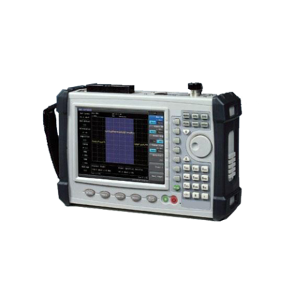
Appearance and Interfaces
Appearance:
Appearance View

Front View

Test Interfaces:
Test Interface Image

The above image describes from the left to right
2048 Hz outer clock Tx, input Rx interface, DS1 and E1 balancing interface, E1, E2, E3, DS3 electrical output, input Rx interface, STM-1 (155M) optical output Tx, input Rx interface, STM-4 (622M), STM-16 (2.5G), optical output Tx, input Rx interface.
Side interfaces:
Right Interface Image

The above image describes from top to bottom
- Power Interface
- 2USD interfaces
- 10M Ethernet Interface
- 9Core RS-232 serial Interface
PDH Interface:
E1 Test interface:
- nominal rate: 2048 Kbit/s;
- Coding: HDB3, AMI.
E2 Test interface:
- nominal rate: 8448 Kbit/s;
- Coding: HDB3.
E3 Test interface:
- nominal rate: 34368 Kbit/s;
- Coding: HDB3.
E4 Test interface:
- nominal rate: 139264 Kbit/s;
- Coding: CMI.
DS1 Test interface:
- nominal rate: 1544 Kbit/s;
- Coding: B8ZS, AMI.
DS3 Test interface:
- nominal rate: 44736 Kbit/s;
- Coding: B3ZS
The common test operation are done by the following test
- E1 Self-Test
- E1 in-service Test
- SDH (155M) Optical Interface Off-Line remote Loop Test
1. E1 Self-Test:
The E1 Self-test is performed by connecting the Tx and Rx in a circle. The test result of Rx should be same with the Tx.
Connect the Device:
Directly connect the E1 Tx and Rx with self-test coaxial cable as follows

Start the software test:
Switch on the system and it displays the system operation window after 30.
Click the Real time test button and run the software
Select the Tx channel and the channel validity is related with signal structure.
Set the parameters and start the test task.
2. E1 in-service Test:
Start the software test:
Switch on the system and it displays the system operation window after 30 seconds as shown in the picture below. Click the Real time test button and run the software.
Set the parameter and configure the frame structure according to the testing signal and connect the device.
Connect the device:
In-service test needs to be bridged over tested line by high-impedance. Connect 2M line and E1 Rx as shown in the picture and start the analysis task.

3. SDH (155M) Optical Interface Off-Line remote Loop Test:
- Connect the device with the tested device by optical interface
- Start the Software test
- Set the parameters and start the analysis test.
Picture shows the device connected by optical interface

Self-Test:
Self-test is used to check the installation status and work status of the modules and the performance and function are normal. Self-Test Interface are shown in the picture.

Main Interface:
Main interface includes the following
- Menu bar
- Tool bar
- Alarm area
- Work area
- Status bar
- Work area display parameter setting
- Analysis task and
- Error analysis
Task analysis and error analysis can be created and deleted freely. When a new task created, task analysis and error analysis corresponds to a tab and a new tab will be added. When some task closed, the tab will be deleted.
Operations:
Error analysis
Error Analysis includes the analysis according to ITU G.821, G.826, G.828, G.829, and M.2100 criterion. Error Analysis events include ES, EFS, SES, BBE, SEP, AS, UAS value and rate. According to the requirements criteria, the testing results counted as acceptable, unacceptable or undetermined. Monitor Point is the error type for error analysis.
Analysis Results include data at near end or remote end, or only the data at near end. Each result display generally value or ratio. The results are as follows
- ErrBits
- ErrBlks
- EFS
- ES
- SES
- BBE
- SEP
- AS,UAS
- Status
Tributary Scan Test
Tributary Scan is to scan tributary status and anomaly/defect information. It is used to scan each tributary at SOH, AU Pointer, High Path Overhead, TU Pointer and Low Path Overhead. According to anomaly/defect information, the tributary status decides the Unload status, Load 0.181anomaly test signal status, Normal status and Anomaly Status. In SDH one STM-1 includes 63 VC-12 tributary, 3 VC3 and 1 VC4.It is not necessary to multiplex and Re-multiplex SDH signal and switch for tributary signal, which is the vital performance of SDH.
TCM Test
Click the task TCM test to start serial monitor test. TCM test includes Tx channel, Rx channel and event record. Tx settings and Rx settings are independent. The following table is the TCM test validity.
| Item | HP (VC4, N1) | HP (VC3, N1) | HP (VC3, N1) | LP (VC1X, N2) | |
| PDH | × | × | × | × | |
| SDH | TSS1, TSS5 | √ | × | × | × |
| TSS2,TSS6 | × | √ | × | × | |
| TSS3, TSS7 | √ | × | √ | × | |
| TSS4, TSS8 | √ | √ | × | √ | |
Test Pattern
PRBS9, PRBS11, PRBS15, PRBS20, PRBS23 and PRBS31.