
Description
Overview
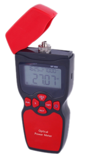
GAOTek Fiber Loss Tester with Power Meter (Functional Testing) is handheld portable device used to measure the return loss in the field fiber optic linking, in order to adjust the quality of the optic fiber end-face, and to make sure the fiber optic communication is in good condition. It specifically measures various optical components, refection attenuation in the optical link and controls the quality of optical fiber connectors. This Fiber Loss tester can realize measurement of Return Loss, Insertion Loss, Output power, and also can be used as the laser source. It is can also provide the on-site optimization solution as the optical RL measurement, IL meter, optical power meter, and optical source. It has the data storage function of 500 measurement items.
Key Features
- Multifunction testing mode (RL, IL, OPM, OLS)
- LCD display
- Testing data can be stored and uploaded
- Simple interface, easy to operate
- Supports USB power supply function
Technical Specifications
| Optical RL Measurement | |
| Test Wavelength | 1310 nm/1550 nm (±20) |
| Spectral Width | <5 nm |
| Output Power | ≥-5 dBm |
| Stability (dB/30 min) 2 | ±0.05 dB |
| Test Range | 0 dB~70 dB |
| Accuracy 3 | ±0.5 dB |
| Resolution | 0.01 dB |
| Connection Type | FC/APC |
| Optical IL(meter) Mode | |
| Wavelength Range | 800 nm~1700 nm |
| Calibration Wavelength | 850 nm, 1300 nm, 1310 nm, 1490 nm, 1550 nm, 1625 nm |
| Display Unit | dBm, dB, xW |
| Test Range | +6 dBm~-70 dBm |
| Uncertainty 4 | ±0.25 dB |
| Power | Three 1.5 V AA batteries/USB powered |
| Working Temperature | 14 °F~140 °F (-10 °C~60 °C) |
| Storage Temperature | -13 °F~158 °F (-25 °C~70 °C) |
| Relative Humidity | 0 %~85 %(non-condensing) |
| Dimensions | 7.08 in × 3.54 in × 1.43 in (180 mm × 90 mm × 36.5 mm) |
| Weight | 0.83 lbs (380 g) (excluding protective coat, battery) |
Additional Information
Applications
- Maintenance in Telecom
- Maintenance CATV
- Fiber Optic Lab Testing
- Other Fiber Optic Measurements
Operation Instructions
Panel Description

Measurement Mode Change
Press button, open the instrument, displaying the state of the last shutdown. Take the RL measurement interface as an example. Interface composition shown below in the RL Interface image below:

When in IL measurement, the unit needs to be changed to IL measurement mode.
Operation as follows:
- Press MENU/ENTER button to enter the menu interface
- Press

 to choose mode, press MENU/ENTER to enter the mode selection interface
 - Press to choose IL Measurement Mode, press MENU/ENTER to enter the IL Measurement

- Press to choose power meter mode, press MENU/ENTER to enter power meter interface

Power Meter Measurement Mode Interface
RL Measurement
- Choose RL Measurement Mode, the interface as in above figure.
- Connect the standard fiber to the out port of the instrument (APC), and then connect the other end of the standard fiber to the measured circuit (Calibration needed before measurement, please see the introduction of RL Calibration). Reading in the instrument is the RL of this circuit.
- When connecting PC to the RL Meter, the laser will be shut down, and the laser state will be. Only restart the instrument after the disconnection, the laser will be open.
RL Calibration
RL Calibration needs a standard fiber. The purpose is to measure the port RL of the instrument itself so as to reduce the difference when to measure the circuit RL. Furthermore, we can also judge through the standard fiber if the system measurement status is normal. Calibration procedure is as follows:
- Connect “OUT” port and “IN” port of the instrument through the standard fiber.
- In the RL Measurement Mode, press to enter the RL Calibration Interface. The screen bottom reading is the laser output power.
- When the reading is stable, press , this reading will be calibrated. The interface after calibration is as shown below:
- Remove the standard fiber connected to the “IN” port, and wrap the mandrel in more than three laps (The Mandrel Diameter ≤5 mm). When the return wave power displayed in the instrument is about -60 dBm, press “REF” to calibrate as shown below:
- Press “REF” again to finish the calibration and enter to measurement interface.
IL Measurement
IL Measurement either uses the internal or external source, below is mainly about the measurement using the internal source. To enter the IL Measurement Mode by the menu:
- Connect “OUT” port and “IN” port of the instrument through the sample line, then select 1310 nm or 1550 nm, and judge if the internal source is emitting by the laser status indicator.
- Press to calibrate the present absolute power reading as shown below:

IL Calibration Finished Interface
After connecting the device under test through the flange or other ways, insert them into the “IN” port. The dB reading now is the IL value of the device measured as shown below:

IL Measurement Finished Interface
Note: When using external source, just insert the source circuit into the “IN” port after connection. Operation is as above.
Power Meter Measurement
In power meter measurement mode, insert the signal under test into the “IN” port. Then read the value directly. In this mode, press REF to set the power reading now as the Ref, UNITS is to change the power unit.
Time Setting
Time setting interface is in “main menu->data setting->time setting” as shown below.

Time Set Interface
Data Save and View
When in the measurement of RL or power meter, press , STORE the save mark will appear in the top right of the screen. After the mark disappears, the current value on the interface will be saved. This information can be viewed in “main menudata settingdata view”. The view interface is as shown below:

Recorded Data View Interface
The system can record up to 999 pieces of data. If you want to delete the data you can operate in “main menudata setdelete all the recordings”.
Backlight Set
When using the instrument, we can control the backlight according to the light conditions. Set path “main menubacklight set”. When the backlight is set in Auto Mode and is powered by the battery, the system will automatically turn off the backlight one minute after no key operation. If powered from outside, backlight won’t be turned off. When the set is “open the backlight”, backlight will remain open.
Switch
Long press , character is displayed on the screen and then release. The instrument is switched on. We enter the measurement interface, press for a short time, the clock logo “” appears or disappears on the top of the screen. When the logo appears it means that the instrument starts automatic shutdown function. When no outside USB power is connected the system will be automatically shut down 10 minutes after no key operation, otherwise, the system won’t be turned off. When need to switch off the instrument manually, long press until the screen becomes dark to finish shutdown.
Sampling Rate Setting
Users can change the sampling rate based on the using situation. There are three choices: fast, medium, slow. You can set in “main menudata setsampling rate set”.
Calibration Power
RL Power Calibration (take 1310 nm for example)
After successful operation, choose the RL Measurement Mode of instrument. After setting the calibrated wavelength at 1310 nm, and the stable desktop source (1310 nm wavelength) is emitting through the jumper (the end must be FC/APC port), connect the source to the standard optical power meter to read the absolute power. Then remove the jumper and insert into the instrument “OUT” port and fill the value measured just now in the box “please fill in the calibration value”. At last click “RL Power Calibration” button, the successful calibration will be displayed on the screen. Now we can see if the reading of instrument is the same as the calibration value (the suggested value is about -15 dBm). Before the light in, the internal source must be turned off through the PC connection, which can be judged by the indicator as shown below:

Calibration of Return Loss Power
Calibration Power Meter Power
The method is the same as the RL calibration, but connect the source to the “IN” port, and put the instrument in the “power meter mode”, then enter the optical power value needed to calibrate in the text box. Click the “calibration power meter power” button to finish the process as shown below:

Calibration Power Meter Power
Other Settings
Data Reading
Click the “content reading” button to finish reading the data stored in the instrument
Add or Modify Notes
After the power reading, double click the cell in the column of notes to add or modify the notes
Data Open and Save
Click the “open” button, you can open the Excel file.
Click the “save” button, you can save all the contents in the list, the path is of your choices.
Time Setting
Enter the year, month, day, hour, minute and second in the input box, then click the ”time set” button to set the time
Exit
Click the “exit” button to close the program
Care and Maintenance
- The instrument needs to be operated in the condition without clear vibration.
- Ensure that the port face is clean when connecting the instrument channel. The port face must be without fat, contamination. Do not to use when dirty and do not use non-standard adapter connector, otherwise it will damage the instrument.
- Carefully insert and remove the optical adapter connector to avoid scratching the port.
- To clean the instrument port regularly, clean the instrument internal port. Please use the special cleaning swab to gently wipe along the circumferential direction.
- Once the instrument is not used, remember to cover it in the protective cap immediately to keep the port clean and to avoid the measurement difference due to dust attachment in the long exposure to the air.
Standard Configuration
| Unit | 1 pc |
| Operation Instructions | |
| Protective Coat | 1 pc |
| 1.5 V AA Battery | 3 pcs |
| USB Data Wire | 1 pc |
| Label | 1 pack |
| Desiccant | 1 pack |
| 5 V USB Adaptor | 1 pc |
| Certificate | 1 pc |
| Warranty Card | 1 pc |
| CD | 1 pc |
| FC/APC-FC/PC standard fiber | 1 cord |