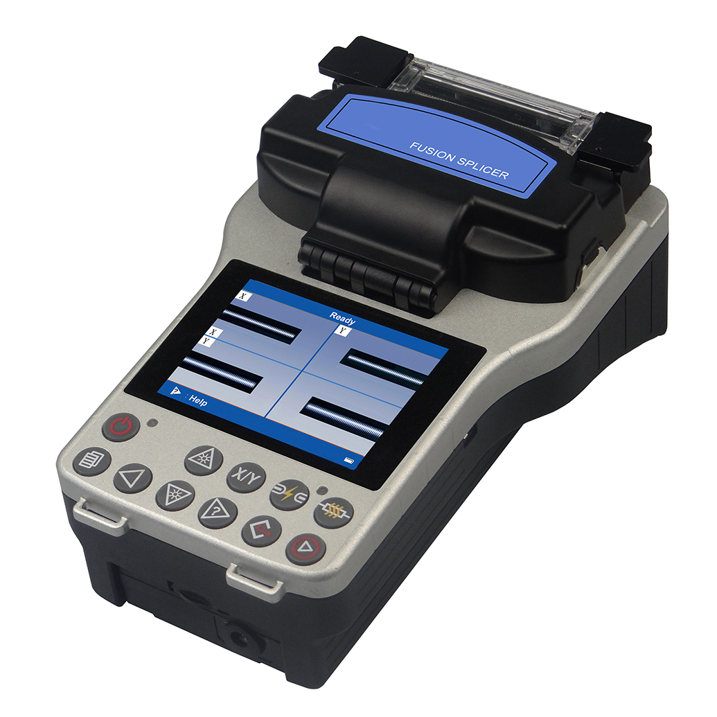
Description
Key Features
- Core-Core & Clad-Clad Alignment
- High-speed image processing and special precision positioning technology
- PAS Technology
- 3-in-one combination clamp
- X & Y view or Single X/Y view display
- SOC available
- Automatic fiber fusion splicing time of 9 seconds
- Real time fusion splicing process compensation in low temperature and low pressure environment effectively guarantee splicing in extreme environments.
Technical Specifications
| Applicable fibers | single mode, multi-mode, DS, NZDS |
| Fiber diameter | Cladding diameter: 80-150 μm |
| Fiber count | Single |
| Fiber cleaved length | 0.47 in -0.62 in (12 mm-16 mm) Coating diameter:250 μm) |
| Actual average splice loss | 0.02 dB (SM),0.01 dB (MM),0.04 dB (DS),0.04 dB (NZDS) |
| Typical splicing time | Typical 9 sec (standard SM fiber) |
| Return loss | >60 dB |
| Splicing mode | Auto Calibrate Normal Special |
| Fiber aligning method | Meticulous, Core, Clad, Manual |
| Tube typical heating time | Typical 30 sec |
| Protection sleeve length | 2.36 in (60 mm), 1.57 in (40 mm) |
| Storage of splice result | 4000 results, 20 parameter per result |
| Fiber image magnification | 120X (X or Y view),60X (X and Y view) |
| Battery capacity | Typical 150 cycles (splice/tube heaty) |
| Monitor | 3.5 inch color LCD monitor |
| Tension test | 2N |
| Electrode life | 2500 |
| Terminal | USB |
| Power supply | AC 100-240 V with AC adapter |
| Inner Li-battery (2600 mAh) DC 13.5 V | |
| Operating condition | 0-5000 m above sea level, 14 °F to -58 °F (-10 °C -50 °C) |
| Max wind velocity of 15m/s | |
| Dimension (L × D × H) | 7.59 in × 4.92 in × 3.34 in (193 mm × 125 mm × 85 mm) |
| Weight | 2.42 lbs (1.1 Kg) including battery |
Basic operation
- Power supply of fusion splicer
The power supply of this fusion splicers adopts two-in-one power supply design. The power supply modes are divided into external power adapter or lithium battery, wherein the lithium battery power supply is divided into built-in battery and independent removable battery. For the correct and safe use of this fusion splicers, the operator must use the parts (power adapter, charger and lithium battery) provided by the company and read carefully following operation manual.
- Power supply of power adapter
The basic parameters of the exclusive AC/DC power supply adapter of the fusion splicer produced by our company are as follows:
INPUT: AC 100-240 V ~ 1.8A 50 / 60 HZ
OUTPUT: DC 13.5 V / 4.8 A
- Power-saving mode operation
To save battery power and based on the work site conditions, the fusion splicer can be set to enter the power saving mode or shutdown mode when the fusion splicer is not operated within a certain period of time.
- Under voltage alarm (battery-powered)
This fusion splicers have “low voltage alarm” function.
The fusion splicer screen will have “low battery!” warning window. Top right corner of the screen has battery under voltage icon and buzzer alarms automatically. At this point, the operator should promptly adopt adapter power supply or charge the lithium battery, hold down for a long time to turn off the fusion splicer. Otherwise, it will shut down automatically after about 30 seconds.
- Start up and shut down
Start up: Press for a long time. When the LED indicator on the keypad is changed to green, release. All motors are back to the initial position, the fusion splicer shows “readiness” screen. The starting up operation is complete.
Shut down: Press. After the LED indicator on the keypad is changed from green to red, Release. The machine completes the normal soft shutdown.
LCD brightness adjustment
On the one hand, the LCD brightness determines power consumption; on the other hand, when the external lighting of the work environment is not the same, in order to facilitate the operation of the fusion splicer, the operator can adjust the LCD brightness.
- Preparation of optical fiber end face
Installing optical fiber shrink sleeve: Before the fiber is spliced, put a fiber heat shrink sleeve in advance on the fiber.
Production of single-mode and multi-mode fiber splicing end face A. Open the big press plate of the cleaver and push the sliding block of the blade from the rear end to the front end.
Placement of optical fiber
- Open the wind cover and wait for the automatic reset of the fusion splicer until the machine is at readiness status.
- Put respectively the prepared fibers into the left and right clamps of the fusion splicer.
- Make sure the optical fiber is placed at the bottom of the left and right V grooves.
- The end face of each fiber shall be placed between the V-groove edge and the electrode center line.

- [splice options] operation
[Spliceoptions] window provides a number of important splicing options. In the readiness window as shown in following figure, move the cursor to [splice options] window and click ![]() button and enter “edit splicing operation option” window. The important splicing options can be set then.
button and enter “edit splicing operation option” window. The important splicing options can be set then.
Overview
- [Splice mode] has 40 built-in users splice modes (splicing parameter files) for different types of fibers to be selected by the users. Three kinds of the default modes included in the machine are: Auto, Calibrate, Normal. Each set of fiber splicing parameter files include the options, important parameters and so on for fiber splicing.
- [Splice mode] has also 53 built-in factory modes (library) or 53 sets of welding parameter files for the special operation by the users (The splice parameter files in the factory mode “Library” shall be introduced into 40 user splice modes).
- Description of menu “select splice parameters file” In different “Mode” settings (including: Auto, Calibrate, Normal), the users can open the splice parameter files with two level permissions. Press
 button or
  button for switching over different windows.
  button or
  button in turn to return back to the original operation window.


Fusion splicing operation:

3. [Maintenance] operations
[Maintenance] function provides a number of important product maintenance options. In the readiness window as shown in following figure, move the cursor to [maintenance] window and click ![]() button to enter “maintenance” window. The important product maintenance options can be set then.
button to enter “maintenance” window. The important product maintenance options can be set then.

- Splice record
“Splice record” function provides the historic records of fiber splices completed before. The machine can store maximum 4000 splice records.
Inspecting splice records
In “splice record” menu, press ![]() button. “view, empty, export” option window appears. When the cursor moves to “view” and click
button. “view, empty, export” option window appears. When the cursor moves to “view” and click![]() button or
button or ![]() button, the window displays the detailed information of current splice record number, as shown in following figure.
button, the window displays the detailed information of current splice record number, as shown in following figure.

Clearing up splice records
- In “splice record” menu, press
 button, “view, empty, export” option window appears.

- When the cursor moves to “empty” and click
 button or
  button, “Delete all records?” dialog box appears. If the operator confirms to clear the current splice record, press
  button or
 button to delete all splice records.

Export splice record
- In “splice record” menu, press
 button, “view, empty, export” option window appears. When the cursor moves to “export” and click
  button or
  button, “save splice record to USB storage?” dialog box appears.

- Insert external U disk correctly into the USB2.0 port on the back cover of the fusion splicer, then press
 button or
  button, soon all splice record information is saved to the user’s U disk.

2. [Settings] Operation
For the convenience of users, [Settings] application menu is provided. In the readiness window as shown in following figure, move the cursor to [settings] window and click ![]() button to enter the “Settings” window. The corresponding options can be set.
button to enter the “Settings” window. The corresponding options can be set.

- Time
The setting steps are as follows:
<1> In the “Settings” menu, move the cursor to “Time” item, press button![]() . “Time” setting window appears, continue to press
. “Time” setting window appears, continue to press ![]() button. “Set Date and Time” and other detailed time information appear.
button. “Set Date and Time” and other detailed time information appear.

<2> In “Set date and time” window, review and adjust year, month, day, and time according to the “keypad prompt bar” at the lower portion of the window.
Monitor position
In order to meet users’ demand in a special environment, this series of fusion splicers are equipped with monitor window rollover function, providing upside and underside options.
<1> In the “Settings” menu, move the cursor to “monitor position” item, Press button. “Upside, underside” option window appears.

<2> Move the cursor to “down” Continue to press ![]() button or
button or ![]() button. All the currently displayed menu of the fusion splicer, fiber splicing windows are roll over, meeting users’ operation demand.
button. All the currently displayed menu of the fusion splicer, fiber splicing windows are roll over, meeting users’ operation demand.

Power save menu
This function is very important to improve lithium battery duration and battery life. When this function is turned ON, the fusion splicer will not operate in the setting time and will enter automatically the sleep state or power off.
<1> Sleep settings “Sleep” feature is disabled by default.

High level operation
The following automatic optimization functions based on optical fiber condition, and the automatic compensatory function in low temperature and low pressure environment.
- Before the fiber is spliced, get by image measurement the end face shape, cutting angle, fiber eccentricity and other parameters of the fiber; and modify accordingly the forward speed and amount of overlap and other splice parameters.
- “AUTO” automatic splice mode: Built-in automatic control splice modes suitable for SM, MM, DS, NZ four fibers. In “AUTO” mode splicing process, by real-time analysis on fiber “thermal image”, the machine adjust and control in real-time the arc time and correct automatically the arc intensity of next splicing, meeting the user’s demand that the splice parameters are always stable when the operation environment changes during the splice .
- “CALIBRATE” self-calibration splice mode: The built-in self-calibration splice mode is suitable for SM, MM, DS, NZ four fibers. In “CALIBRATE” mode: the fusion splicer gets and analyzes the characteristics of the fiber “thermal image” before welding. After finishing the analysis, the machine corrects automatically next splice arc intensity according to “estimate splice loss”. This splice mode is used by the factory for the configuration of different types of fiber optics.
Select splice mode according to the type of optical fibers
<1> Different fibers have different splice parameters. In the fiber splice operation, the user shall choose a suitable fiber splice mode according to the type of fibers to be welded.
<2> In “Select splice parameter files” screen, there are a total of 12 sets of different kinds of fibers.
Splicing operation
This series of fusion splicers are installed with an image processing system to observe and inspect the optical fiber. However, the image processing system may not discover fusion splicing errors in some cases. In order to achieve good welding results, the operator needs the LCD to monitor visually the entire welding process of the optical fiber. The following describes the standard welding steps.
- Inspection on cutting angle and end face of the optical fiber
Two optical fibers are loaded into the fusion splicer and are moved forward each other. After cleaning arc, two optical fibers are stopped respectively at a set position. The operator shall then check the cutting angle and the quality of the end face of each fiber. If the measured fiber cutting angle is bigger than the set limit (factory default value), or the operator checks out the end face of the optical fiber has a burr, the machine buzzer alarms. At the same time, the LCD will show an overrun alarm message. Fiber splicing process is paused automatically. To ensure the quality of welding, the user is recommended to make again a good fiber end face and place the fibers into the machine once again.
- Automatic aligning and splicing
After optical fiber inspection is finished, the fibers will be aligned according to the manner of “core to core” or “clad to clad”, and then is spliced with arc.
- Estimation of splice loss
After fusion splicing is finished, the estimated value of the splice loss will be displayed.
- Screen Data Description:
Core: The left fiber core is offset to the right fiber core. Clad: The left fiber clad is offset to the right fiber clad. Fiber: angle between the left fiber (extension line) and the right optical fiber (extension line) on X (Y) screen. H: Angle between the left (right) fiber and the horizontal line. V: Angle between the left (right) fiber end face and the vertical line.
Saving splice records
Upon the fiber splicing is completed and the loss estimate is displayed, the splice loss value, splice parameters, splicing time and other relevant information will be stored automatically in the machine’s memory. When 4000 splice results have been stored, 4001th result will overwrite the first result.


